Hey everyone, so I thought I’d make some documentation for people wanting to weld in the future. This is by no means official or professional, it’s just an album with photos from whenever I remembered to take one during the chassis welding process. So use this to get an idea of what’s going on, but know there is a LOT of missing information here. Let’s go!
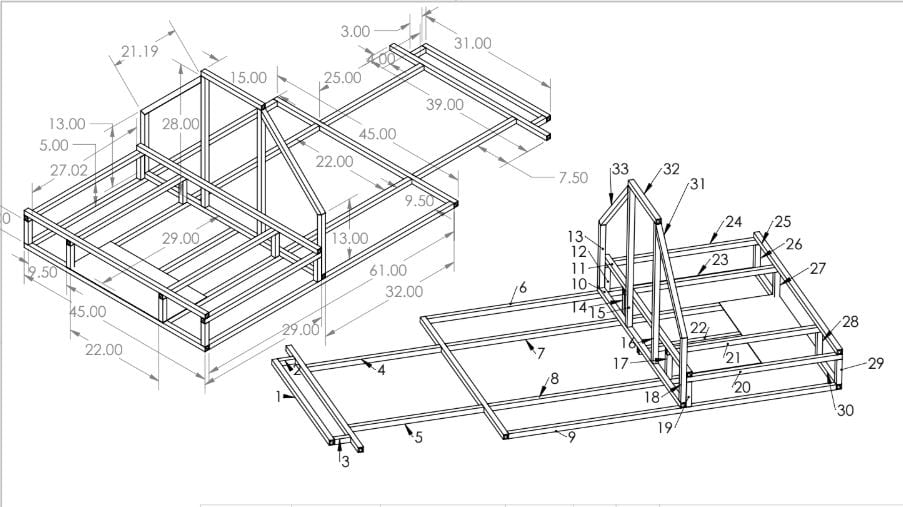

(1) The first step is to get organized! To facilitate our welding process, Marco and I backed out dimensions from Solidworks on to an orthographic drawing of our chassis CAD.
(2) Here I’ve put all the members we cut with the Johnson saw onto a cart, arranged by length. The purpose of the bricks is shown further down.
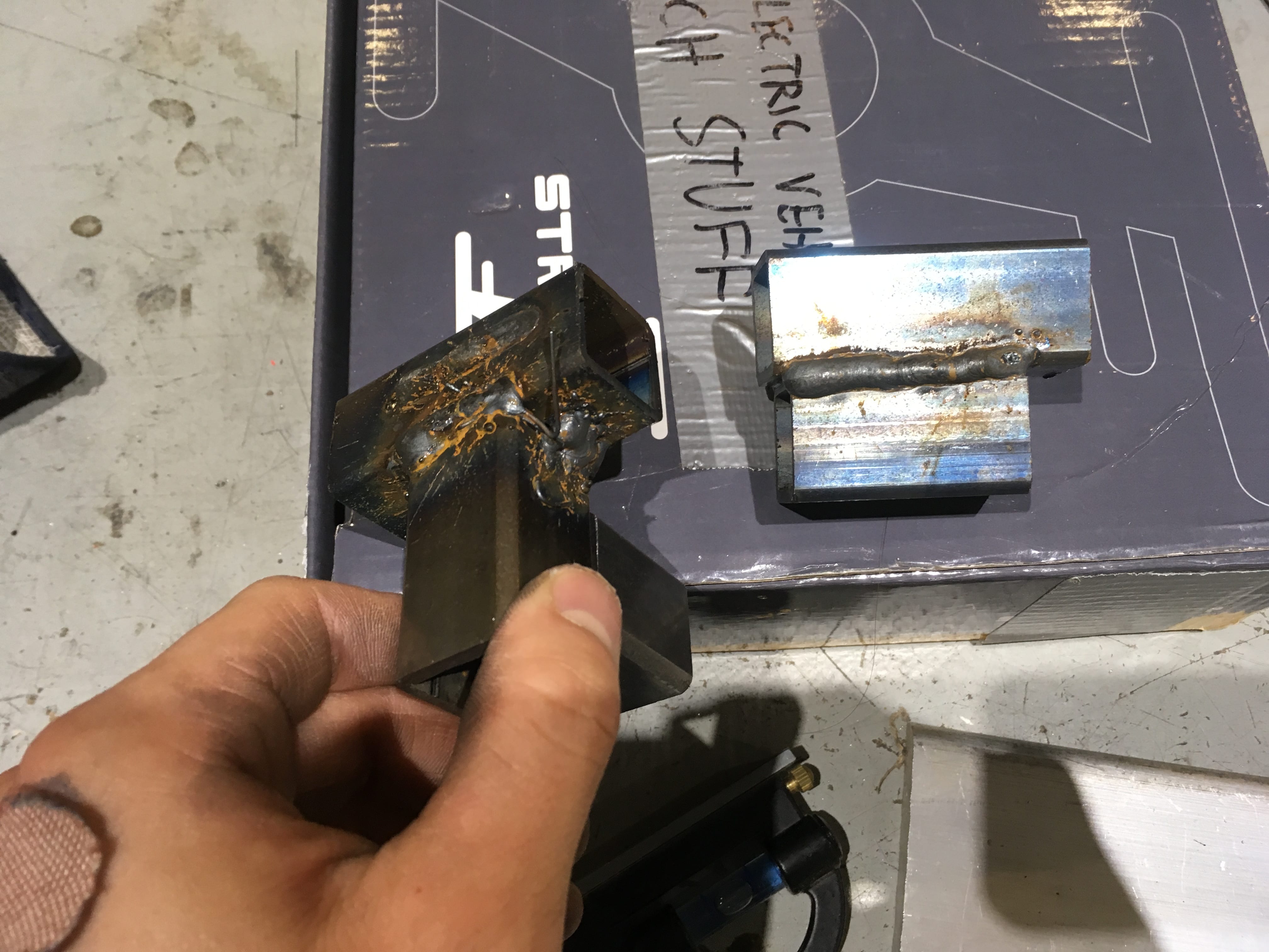

(3) Can you spot the differences between the left and right pieces in photo (3)? One has crappy welds, and the other one is cleaner. This is because the square tubes we bought shipped with some kind of oil/metal dust/something coating it, which messes with the welding process (Long answer: prevents the arc from forming consistently across the nonconductive coating and reaching the metal, through which current returns back to ground – circuit is interrupted).
(4) To remedy this, we used the wire brush in the welding shop to scuff and clean the surfaces to be welded together (to expose the naked metal for better conduction). This was the process used in the right piece in pic (3), which is why the weld came out much cleaner than the left one. The wire brush has an on/off toggle switch, super simple to use. Be sure to wear safety glasses and gloves.
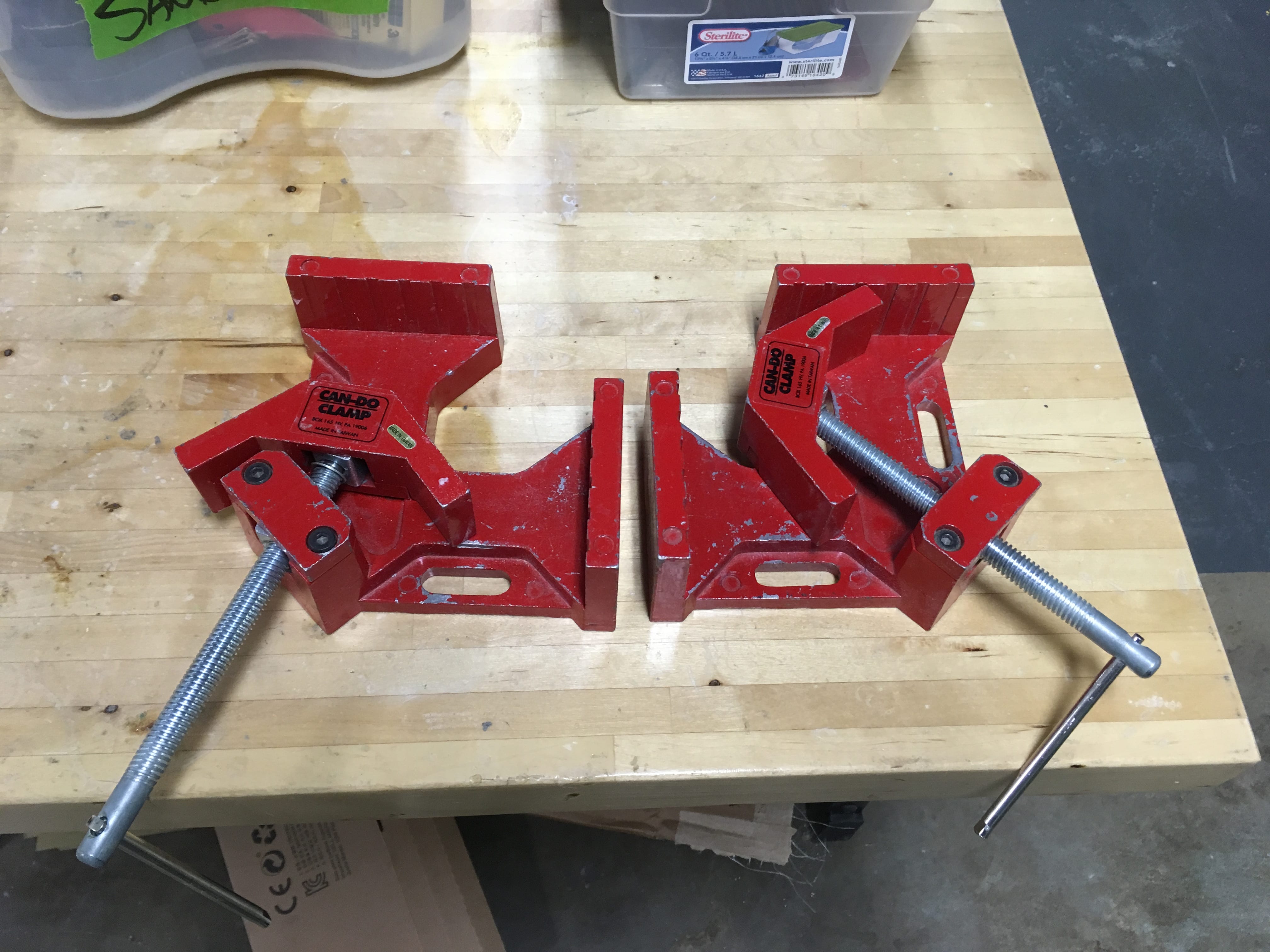
(5) We ‘borrowed’ some square clamps from the OEDK in order to join tubes at 90 degrees for the chassis’ main frame (and some parts of the front subframe.
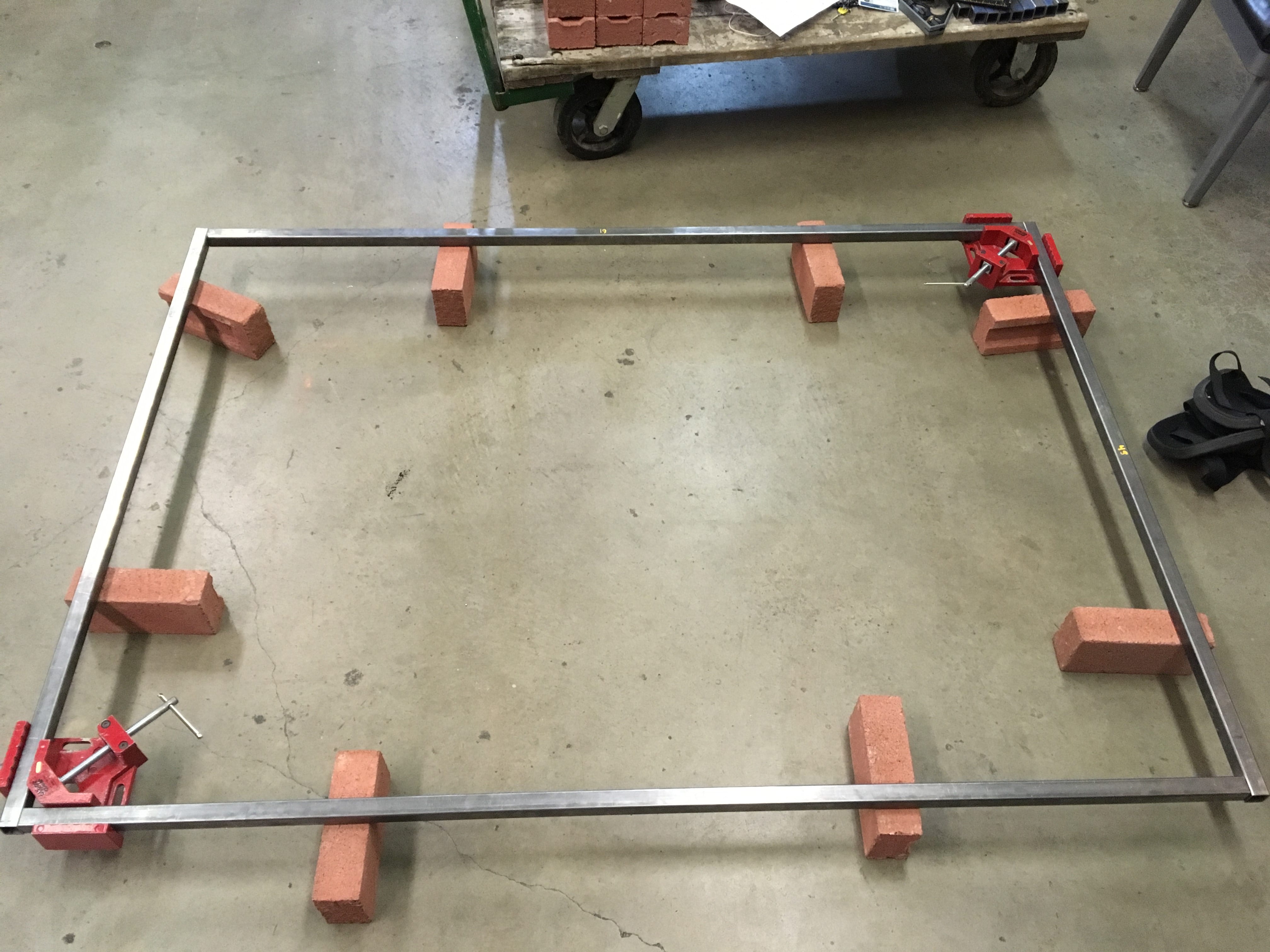
(6) Setting up the main ‘square’ (I am aware that it’s not a square) of the frame using said clamps. We used bricks to support the frame, because it’s hard to get pieces level on the floor, and welding on the floor is a pain.
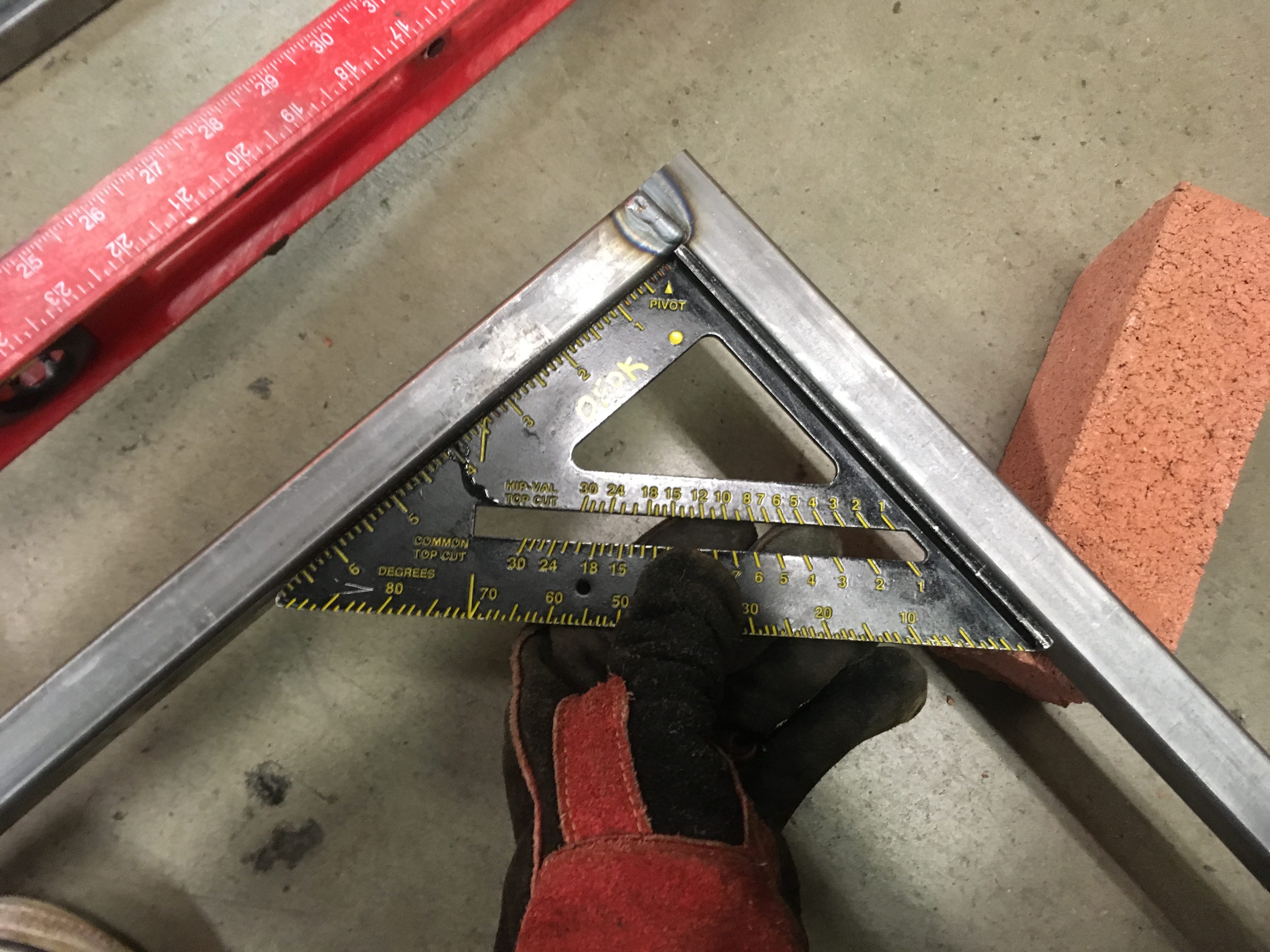
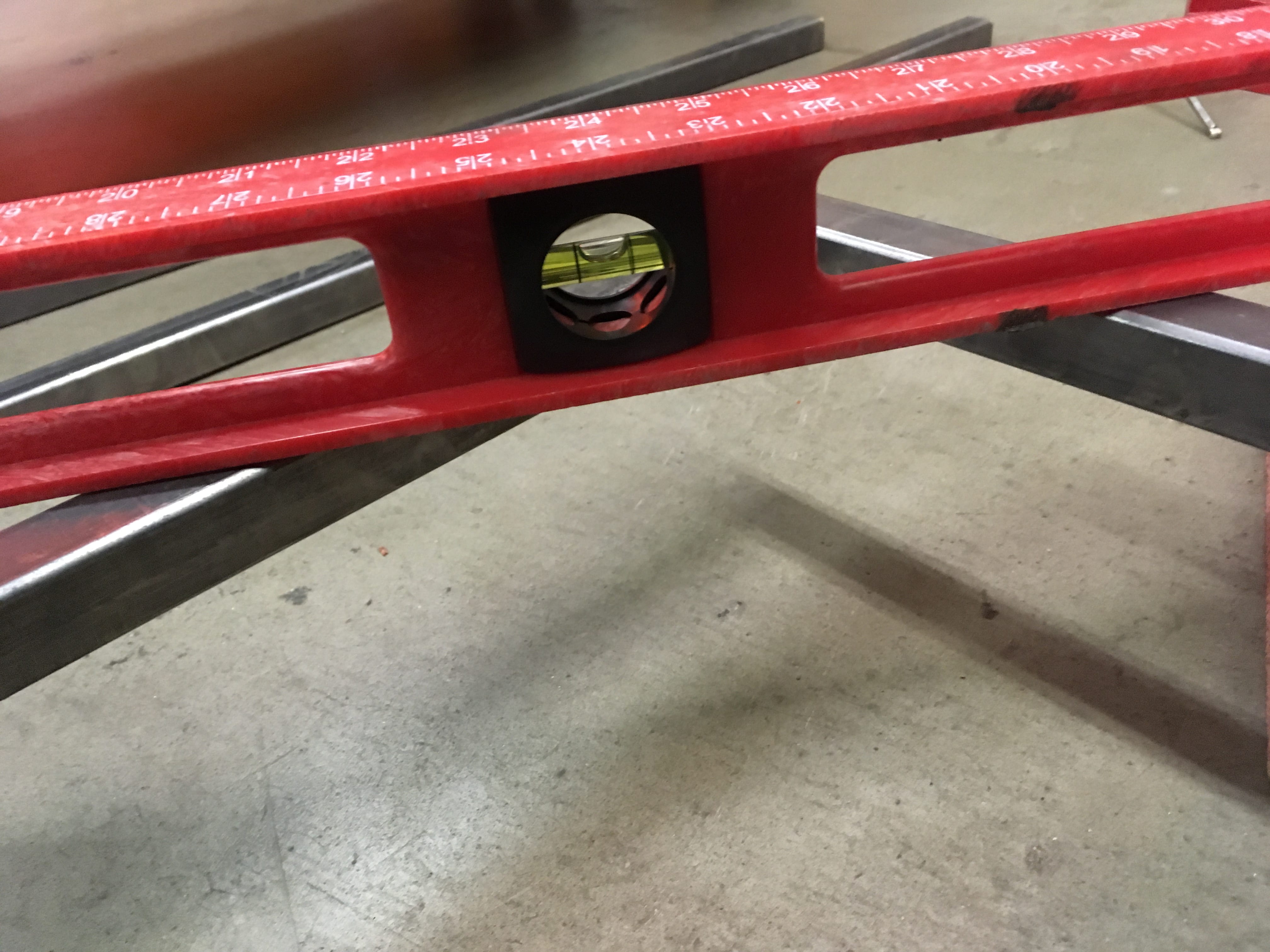
Using a speed square (7) and bubble level (8) to check that my joints were square and level. These photos were taken after I had already welded those joints, but I promise I checked before I welded too. It’s good to check both before and after, because the heating and cooling during welding can cause metal to ‘pull’ in one direction or another (thermal expansion), which can throw off dimensions and cause misalignments.
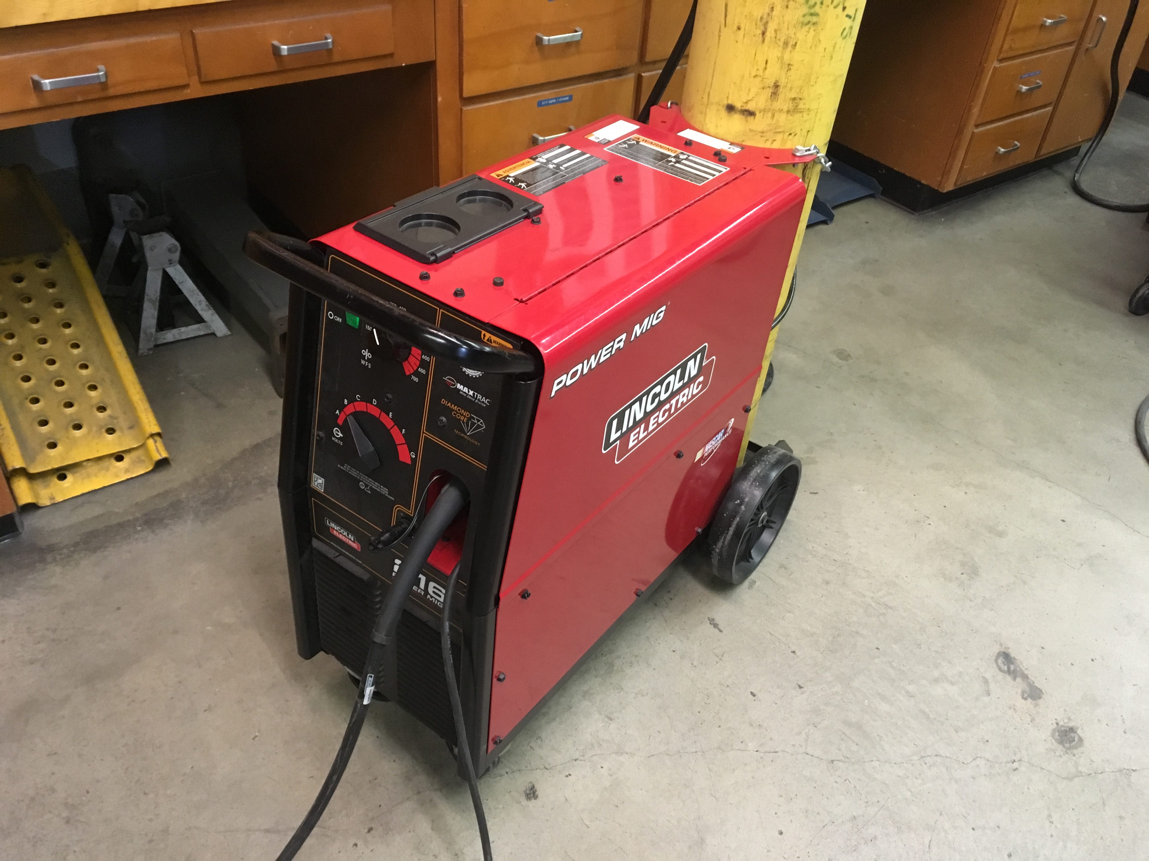
(9) The MIG (Metal Inert Gas) setup we use. Your “pre-flight check” should be: (a) Shop vacuums on, (b) MIG welder on, (c) Ground clamp connected, and (d) Gas valve open – look AWAY from the tank when opening the valve. If you don’t know how to weld, grab someone who does, and they’ll go over this in more detail with you
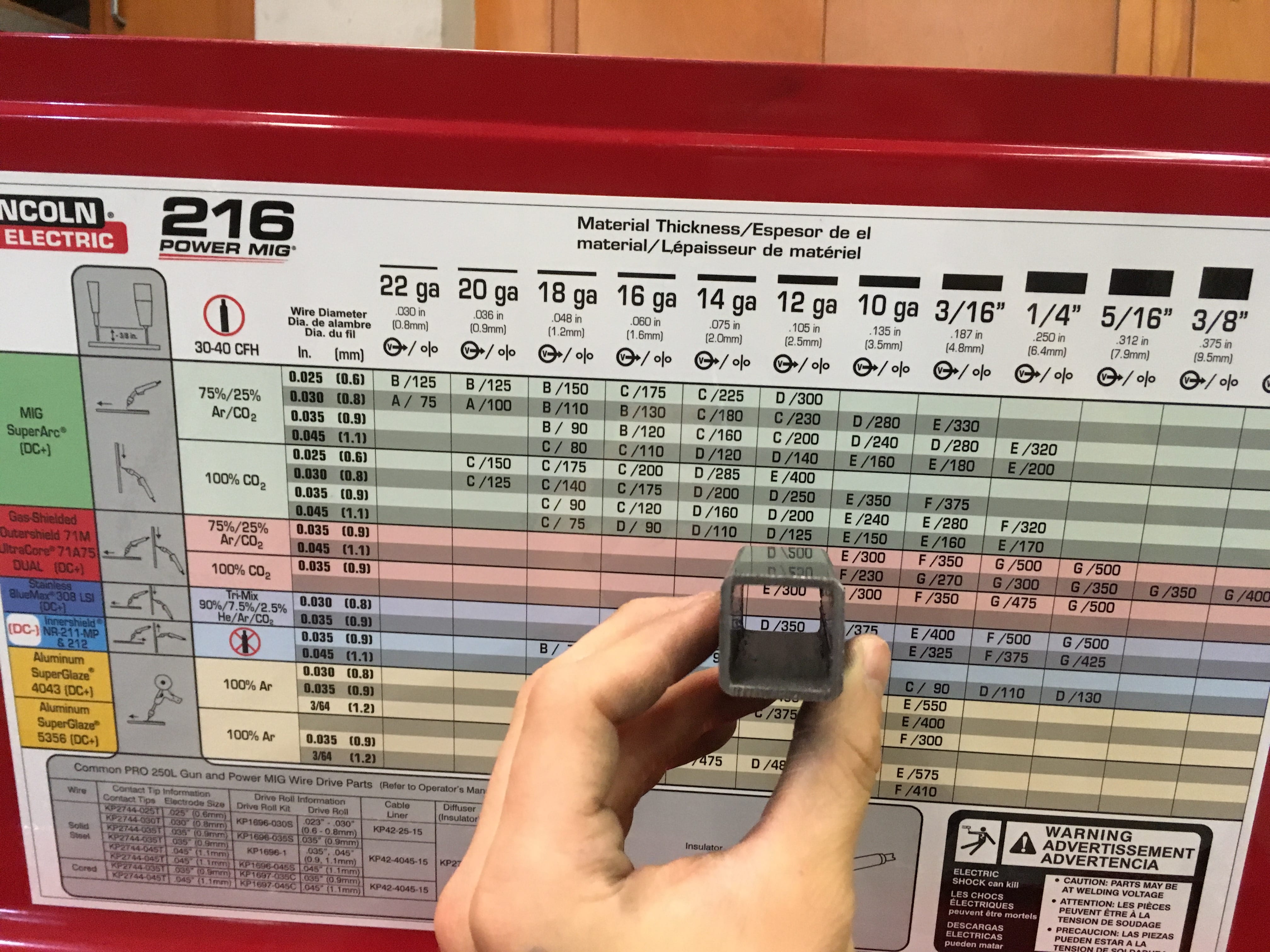
(10) Use the handy-dandy table on the inside of the welder to figure out the Voltage and Feed Rates, which depend on the thickness of your filler wire, the mix of shielding gas, and thickness of the material to be welded. Again, I won’t go into too much detail here, because you new welders should be going with someone experienced anyway, and they’ll show you what’s up.
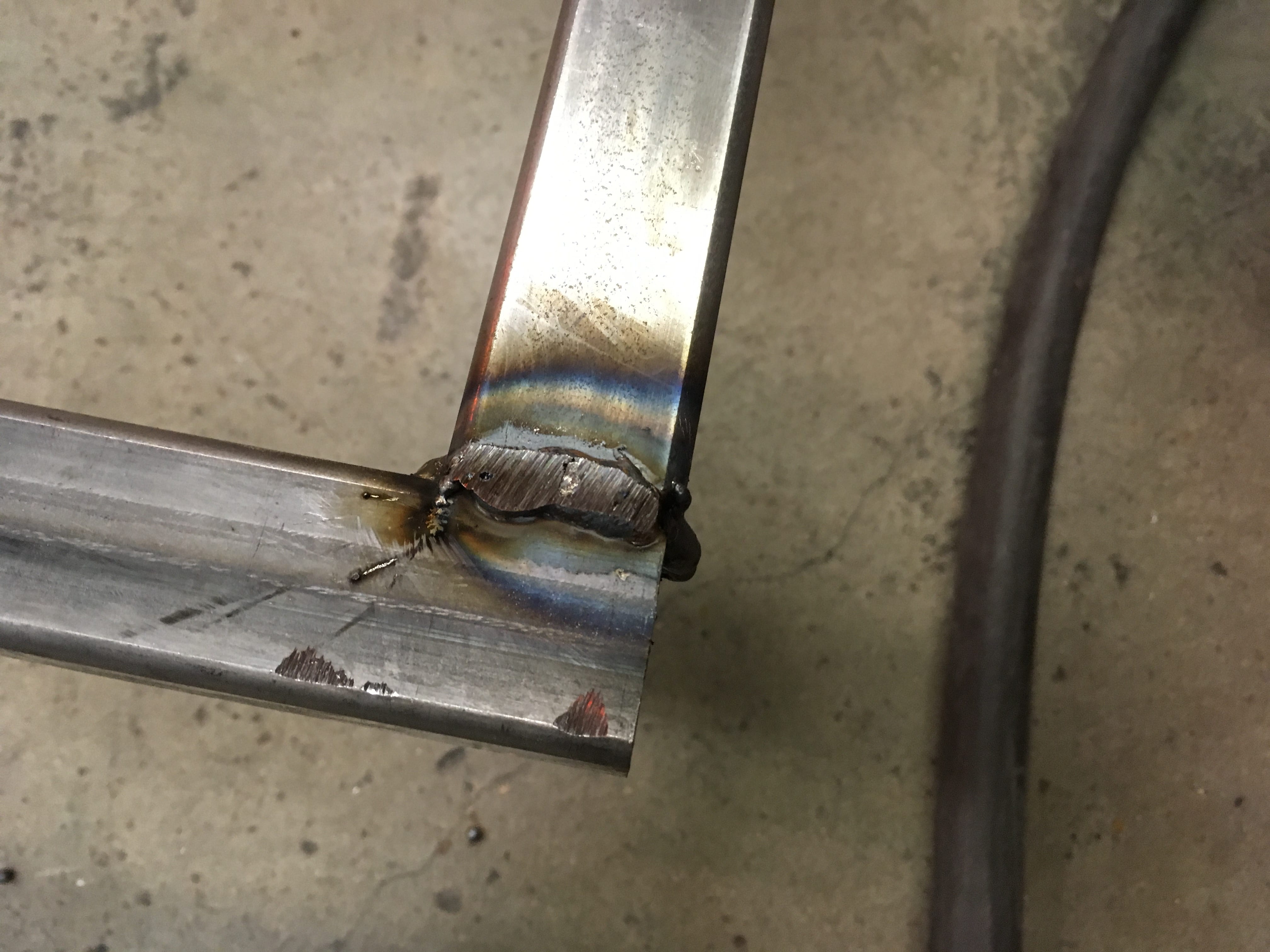
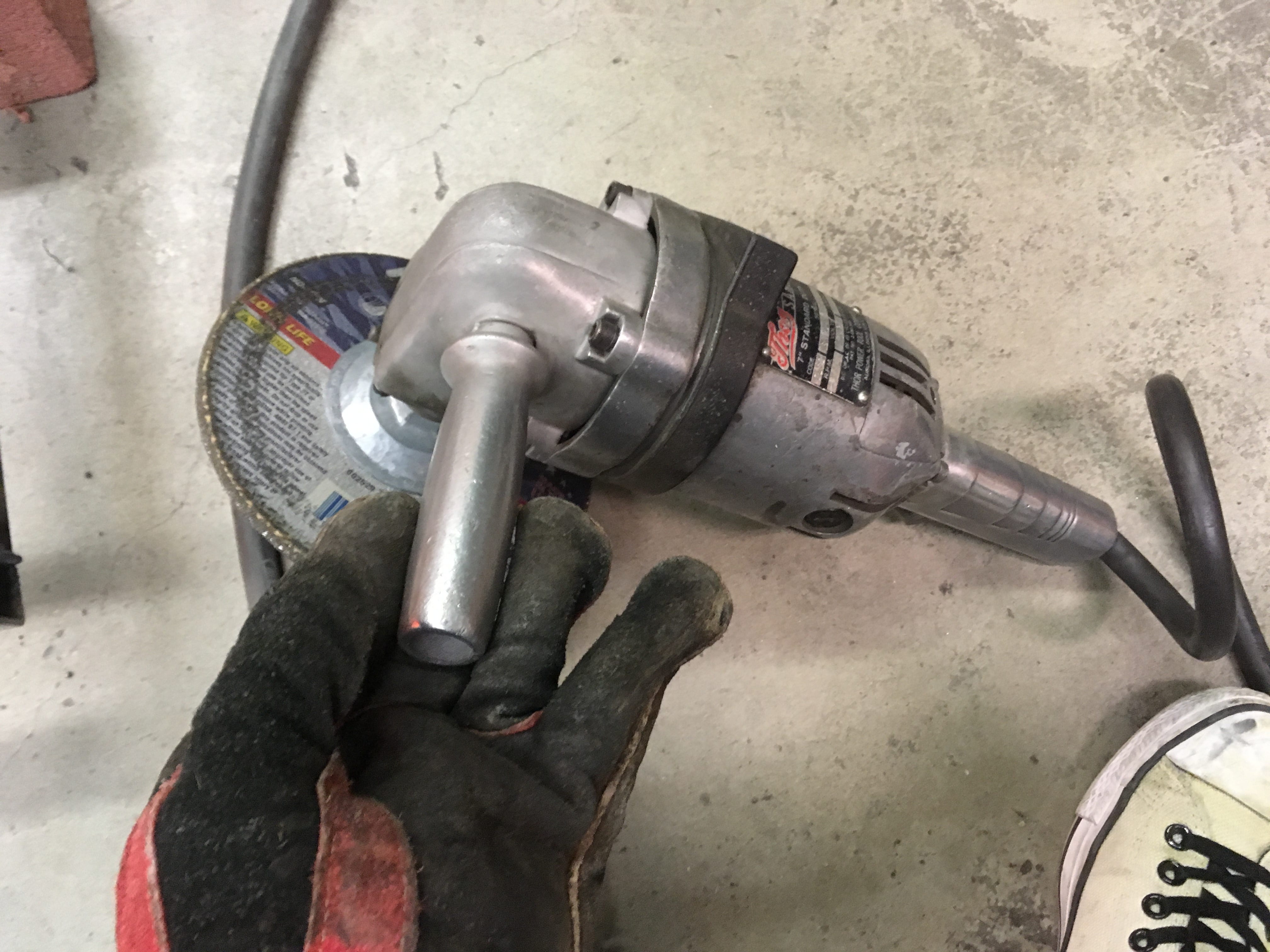
(11) Post-weld, I tried to clean up the pieces with an angle grinder (12). This step is probably overkill in most scenarios though.
